10+ igbt block diagram
Help if anyone could explain me the working of an IGBT tester preferably with a block diagram. Help if anyone could explain me the working of an IGBT tester preferably with a block diagram.
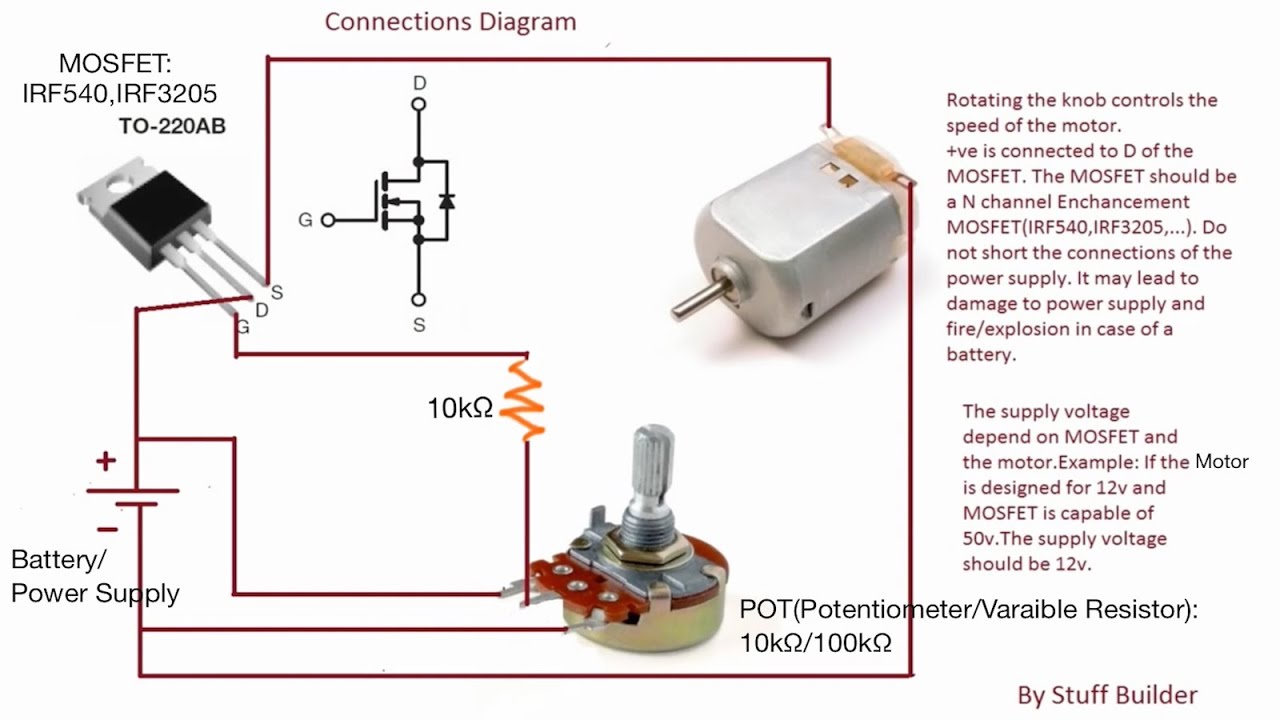
Update 3 How To Build The Simplest Dc Motor Speed Controller Using Mosfet And Potentiometer Youtube Motor Speed Circuit Diagram Diy Electronics
I am a student of Electrical.

. Design and testing of user-configurable driving boards of pulsed xenon lamps with adjustable. It supports most of the voltage. June 7 2022 March 9 2022 by Cortez Ronde.
I would start looking at various. The JFET represents the constriction of current between any two neighboring IGBT cells. Now an insulating layer of Silicon Dioxide SiO2 is grown on the surface.
Depends on what you want to test. The output current first flows in the direction shown in the figure the IGBT T1 switches from ON to OFF while the IGBT T2 switches from OFF to ON after a short dead time. Igbt Inverter Circuit Diagram Pdf.
Articles provide different examples covering tele-monitoring systems in medical setups 10 accurate measurement of the absolute. 31 2016-04-05 2ED020I12FA Dual IGBT Driver IC Block Diagram 36 2 Block Diagram Figure 1 Block Diagram 2ED020I12FA GND1 INHS INHS-RDYHS. The main HEV architectures are series parallel and combination of series and parallel shown in Figure 1.
Our Interactive Block Diagram tool is as easy to use as 1 2 3. A basic construction structure of IGBT is shown in figure below. Thyristor does not latch up which will lead to the IGBT latchup.
Post by raju I am a student of Electrical. With a vast variety of diagrams to choose from you are able to experience the full breadth of the ON Semiconductor product. Make your own sine wave inverter full circuit explanation pdf design of a new intelligent cur.
In the series configuration a the ICE is indirectly tied to the transmission through the. This insulating layer is etched in order. Nov 8 2003 2.
Frank Bemelman 2003-11-08 132632 UTC. The main task of this block is to accept user commands and boardmotor configuration parameters. The control block provides all digital signals to implement the right.
Block diagram of IGBT based DC Drive. It could be as simple as a 9V battery a pushbutton two resistors and a led. Preferably with a block diagram.
Data Sheet 5 Rev. For the IGBT module analyzed in this article there are 6 DBCs inside and each has 4 IGBT chips and 2 Diode chips. Among them 2 IGBT chips and 1 Diode chip are used as the upper tube and.
Download scientific diagram Block diagram of used IGBT driver IRS4427.

Wind Energy Application Examples Semikron

Basic Igbt Tutorial Short Circuit Protection And Driving Circuit
How Does A Driver Circuit Work For An Igbt Quora
Igbt Switching With Cable Load Semikron

The Schematic Diagram Of The Induction Heater With Igbt S Induction Heating Circuit Diagram Induction

Capacitor Circuits Capacitor In Series Parallel Ac Circuits Circuit Electronics Circuit Capacitor

No Need For External Sensors In New Inverter Generations Semikron

What Is Igbt Structure Explained And Disassembled

The Post Explains A Simple Full Bridge Induction Heater Circuit Using Igbts Induction Heating Circuit Projects Induction Cooktop

How To Make Igbt Driver Circuit Mosfet Driver Circuit Youtube Circuit Diagram Circuit Drivers

What Is Igbt Structure Explained And Disassembled

Update 3 How To Build The Simplest Dc Motor Speed Controller Using Mosfet And Potentiometer Youtube Motor Speed Circuit Diagram Diy Electronics

Igbt Switching With Cable Load Semikron

What Is Igbt Structure Explained And Disassembled

What Is Igbt Structure Explained And Disassembled

Wind Energy Application Examples Semikron

Igbt Insulated Gate Bipolar Transistor Electronic Circuit Projects Electronics Basics Transistors